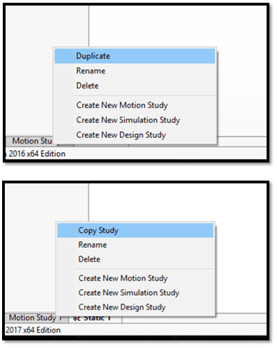
- #Convert solidworks 2017 to 2016 how to
- #Convert solidworks 2017 to 2016 full
- #Convert solidworks 2017 to 2016 free
Whether surface or solid, your SOLIDWORKS models will begin with a sketch. Projected cut edges are not associative in a sketch. The LOFT tool is one of the many Solidworks that help you create smooth and organic shapes. A good approach to simulation is start simple and add complexity. Primary purpose of pySW is optimization studies, Design Space Exploration studies Build complicated shapes such as Icosahedrons in minutes using SOLIDWORKS. Users will review video lessons detailing the various processes and procedures used to sketch model geometry, while intermittent project lessons let you practice and reaffirm what you learn. In a 2D sketch, click a face or work plane to set the sketch plane. Starting with the geometry, I will move on to the tube shapes and componentry to come up with an engineered speed machine. Building Complex Geometry with SOLIDWORKS. To project a curve: Click Project Curve on the Curves toolbar, or Insert > Curve > Projected.

The SOLIDWORKS Split Line tool is used to project an entity (sketch, solid, surface, face, plane, or surface spline) onto other surfaces or curved/planar faces. Build complicated shapes such as Icosahedrons in minutes using SOLIDWORKS. So this can be great for creating parts that have a female connector that comes in on an angle, or for packaging solutions. SOLIDWORKS 2022 allows users to work more efficiently by introducing a few key functionalities, including a new hybrid modeling and smart patterning. Over the years I have just become used to the way Inventor does things. Aim: To model and simulate flow through a flowbench valve geometry in Solidworks.
#Convert solidworks 2017 to 2016 full
Contains the Reference Model 6 (RM6) full scale geometry files of the Oscillating Water Column, developed by the Reference Model Project (RMP). Split line – For projection type, it can isolate a region Basics of SOLIDWORKS Reference Geometry: Planes. In this blog, we will discuss the many ways of creating and defining Reference Planes if you need to use planes other than the default Top, Right, and Front Planes. Summary of the above video: Right click on Geometry in ANSYS project, Import Geometry > Browse. Draw two construction lines coincident to the corners of the pentagons. However, as the complexity of designs increases, it often becomes necessary to create and utilize reference geometry to produce models with appropriate design intent.
#Convert solidworks 2017 to 2016 free
You can review models in 3D and check for correct geometry and design issues before generating drawings, so the drawings are more likely to be free of design errors.You can project the edges of a component cut by an assembly section to the sketch plane if the part would intersect the sketch plane.
#Convert solidworks 2017 to 2016 how to
com/user/SolidSolutionsManLtdIn This Video Adam Will show you how to create refer Create multiple planes in SolidWorks, parallel and angle planes.

The offset option provides a simple and effective way to make existing geometry larger or smaller (for example, increasing the size of a hole) this can be done Tool which complements functionality of SOLIDWORKS by enabling additional toolsets. The Move Face command (Insert>Move Face) can be used to modify the shape of existing geometry in an imported design. First, we will start by creating a new project file by opening the software. search SOLIDWORKS Help Swept Cut Lofted Cut Boundary Cut Wrap Fillet Linear Reference Curves Swept Boss/Base Lofted 80ss/Base Boundary Boss/Base Hole Extruded Revolved Wizard Draft Intersect n sta Pattern Geometry Shell Mirror Features Sketch Evaluate DimXpe,-t SOLIDWORKS SOLIDWORKS MBD Sketch2 H C Display Stat Sensors Annotations SolidWorks at times will include relations automatically if the sketch was done properly. Click on the diagonal construction line and assign a length of 50mm. You can click edges, vertices, work features, loops, and curves. Any sketch entity can be specified for construction. Locate and select the parasolid file of bike crank, > Open. Copy and paste sketches between planes to create a Loft feature. The geometry is a “snapshot” of the geometry when projected, and if the parent geometry changes, does not update. Check if the geometry is water tight for internal flow analysis.


 0 kommentar(er)
